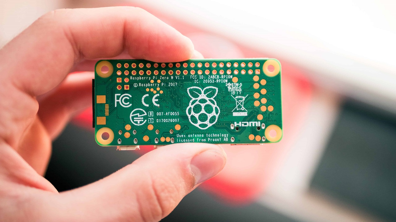
Printed circuit board diagrams that are termed as schematics are the line drawings that show how these components are connected. We may call these diagrams a map or a plan for the assembly process of electronics projects.
You can read these circuits easily. The reading process is far more comfortable than their actual work. You can even read the schematic diagram even without understanding the functionality of the circuit.
You can get the schematic on many quickly built electronic devices. You have freedom of choice. Two things compose the schematic diagrams. These are as under:
- Symbols are used to represent components in the circuit.
- Lines are used to representing the connection between the components of circuits.
Here is the description of connections to provide you a better understanding.

1. Connections
In-circuit diagrams there is a demonstration of wires and other conductors that do not mingle with one another. They offer no resistance at all. If you see the line between components, it is a depiction of their connection, and then there is a period. It is only a depiction of the connection without interference.
The connection may be of different kinds. It may be a wire, copper trace, or a plug socket connection. The electricity runs through it without offering any resistance.
If there are messy details about wire and cable specification, you may find elsewhere in the document. The length of the line is no more a description of the range of connection.
The real-life distance may not be related to connection distance. These schematic lines are clear and easy to read. To minimize the clutter, the components ad connections are arranged on the page. They are not the representation of a method to place them on the circuit board.
Now we have information about lines if two lines cross. It is not the representation of a 4-way connection. The schematic differentiated between the unconnected paths and junctions where the line crossings show a shared connection.
There is a dot over the line intersections that demonstrate the connection. It shows that if there is a crossing without a dot, it is not connected. `
If there is a three-way intersection, it will mean that a three-way connection exists, even if there is not a dot. But some people follow a dot drawing procedure for three-way connections, and others don’t see it is needed. You bring a connection to nowhere.
Schematics also represent the connection between different types of power and ground. On the schematic, you may see a power symbol in different places.
It means it is connected to the same place or a conductive object. There are power connections that are represented without symbols. A label represents V+ or 5V, and 12V.

2. Components
The component is shown by a symbol that determines the general type of components. There may be a label that may point to its specific features.
The labels in formal schematics are parts designator. It is a code that consists of one or two letters. A unique number that follows it represents circuit types, e.g., resister R1. There are also other schematic component specifications included.
The resistor specs often come with a capital omega to avid special characters. Each component symbol has connecting points. The lies can be drawn to these connection points.
Each component symbol has several connections where you may draw the line. These lines are related to leads of the physical component.
For resisters, the ceramics capacitor lead connecting method does not matter. But in other components, the leads have a set orientation.
There is a datasheet for every component that a manufacturer publishes. The datasheet associates the physical terminal with their functions. Connection points indicate it.
Integrated circuits such as chips may contain ivied electronic components into small blocks. The numbers of connection terminals run along the sides. Some schematics swap IC, s leg around, and put them into a rectangle shape; PINs label these.
Physically chips are single component, but so far as functions are concerned, there is some multiple independent component hat combined in the single package.
In these conditions, you may diagram a chip physical y or functionally. You may use separate symbols for functional components that are on the clip. In this way, you label them clearly to show that they o the same chip.
You will note that working drawings show power and ground connections to the chip. If a circuit diagram is determined by chip using its functional components, you should understand and need to hook up power and ground as well.
You should make sure that the schematic does not show them. The datasheet is an excellent help for you. It would help if you considered connecting the identical-looking legs properly.
Schemas are a map that shows how to connect discrete components. There is a standard and easiest method to translate the most schematics into the working circuit.
You should use ingredients with standard pin spacing and then connect these components on a solderless breadboard using jumper wires.
After the process, you may evaluate connection and otherwise debug if there is an issue. You may understand and assess the circuit with a millimeter. You need to test it before you consider it is joining with the solder.
Here are the main points that you can read and build a schematic diagram. You may have an understanding of the circuit if you know How to decipher the printed circuit board diagram.
Important points
- There are two things involved in schematic diagrams: symbols and lines.
- The line shows that components are connected, and it does not tell you more.
- Schematics are used to differentiate the unconnected paths.
- There are some special symbols used in schematics to show the types of power and ground.
- A symbol and a label represent the circuit component.
- There are some connection pints for each symbol.
- The diagrams on chips represent physics or functions.
It is how to How to read printed circuit board diagram.
If you want to learn more about printed circuit boards, I suggest you visit this blog: https://www.pcbonline.com/blog/.
Tech India Today
Related posts
Recent Posts
- How Important is Competitor Analysis? November 13, 2023
- Securing the Internet of Things: A Growing Concern October 2, 2023
- When DevSecOps Shines: Reinventing Software Development May 17, 2023
- Implementing Infrastructure As Code (IaC) With DevOps April 21, 2023
- What Can You Gain By Choosing a Reputable HVAC Software Solution? March 19, 2023
Categories
- Artificial Intelligence (AI) (18)
- Augmented Reality (AR) (5)
- Automotive (7)
- Blockchain (2)
- Business (45)
- Career (4)
- Cloud Computing (6)
- Computers (4)
- Content Management System (1)
- Cryptocurrency (1)
- Cybersecurity (7)
- Data Science (1)
- Digital Marketing (32)
- E-commerce (1)
- Education (6)
- Electronics & Hardware (10)
- Entertainment (5)
- Finance (9)
- Gadgets (23)
- Games (3)
- HTTP (3)
- Industry (2)
- Infographics (3)
- Internet (138)
- Internet of Things (IoT) (22)
- Job (3)
- Lifestyle (2)
- Machine Learning (7)
- Marketing (45)
- Marketplace (2)
- Mobile Apps (20)
- Natural Language Processing (2)
- Network (15)
- News & Trends (15)
- Operating System (OS) (6)
- Programming (10)
- Robotic Process Automation (RPA) (13)
- Security (19)
- SEO (24)
- Social Media (29)
- Software (35)
- Tech India Today (1)
- Technology (166)
- Virtual Reality (VR) (2)
- Web Apps (12)
- WordPress (1)
- Workflow (2)
- Workforce (2)
- Workplace (1)
- Workspace (1)

